A conceptual data model is a high-level view of how key business entities relate to one another, and helps you understand the structure of your data before getting into technical details. By focusing on business concepts and relationships, a conceptual model enables you create a unified view of business entities early in planning.
It ensures clarity and shared understanding before moving to more detailed logical or physical designs. This is achieved via entity relationship diagrams.
Conceptual models include the following components:
-
Entities: Objects or concepts that represent data within the system.
-
Relationships: Associations between entities that define how they interact. You can create the following types of relationships in a conceptual model:
-
Identifying
-
Non-identifying
-
Many-to-many
-
This topic explains the following processes for conceptual modeling:
Creating Conceptual Models
To create conceptual models and objects, and define their relationships, follow these steps:
-
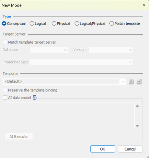
In erwin DM, click File > New.
The New Model screen appears.
-
Click Conceptual.
-
To create a blank conceptual model, click OK.
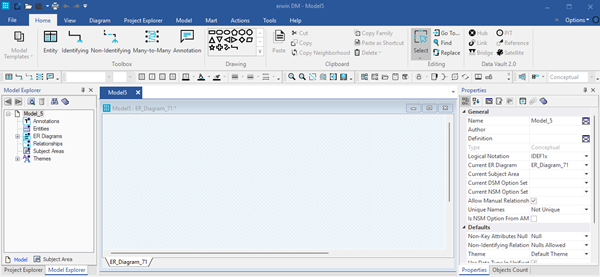
A blank conceptual model is created.
-
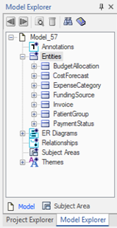
On the ribbon, click Home > Entity, and then click in the diagram window to add the entity.
Similarly, you can add more entities and relationships in the model. Entities and relationships can also be added from Model Explorer.
You can create, derive, and compare conceptual models. You can also generate reports using report designers. However, some capabilities aren’t supported for conceptual models.
Unsupported capabilities:
-
Model Template
-
Project Explorer
-
Spy
-
Query Tool
-
Forward Engineering
-
Target Database Change
-
MITI Bridges
-
Attribute Editor
-
Index or Keygroup Editor
-
Paste as Shortcut
Deriving Conceptual Models
Consistency across design layers starts with reusing objects from existing models. By deriving new models from existing ones, you simplify the modeling process, reduce duplication, and ensure that related models stay aligned with both business and technical requirements.
When working with conceptual models in the design layer, you can:
-
Derive conceptual models from logical models or from other conceptual models.
-
Derive logical models from conceptual models.
You cannot:
-
Derive conceptual models from physical models or logical/physical models.
-
Derive physical models or logical/physical models from conceptual models.
To derive models from conceptual model, follow these steps:
-
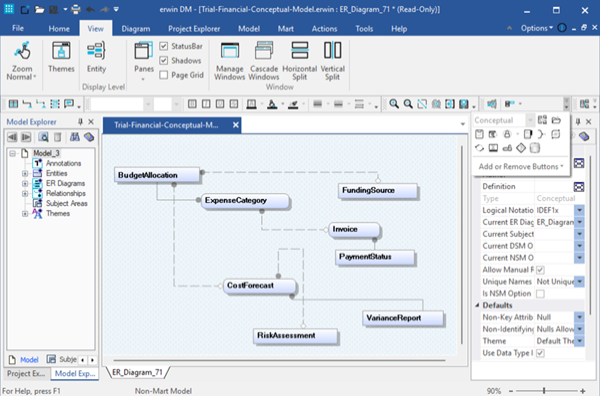
Open an existing conceptual model.
-
On the ribbon, click Actions > Design Layers > Derive New Model.
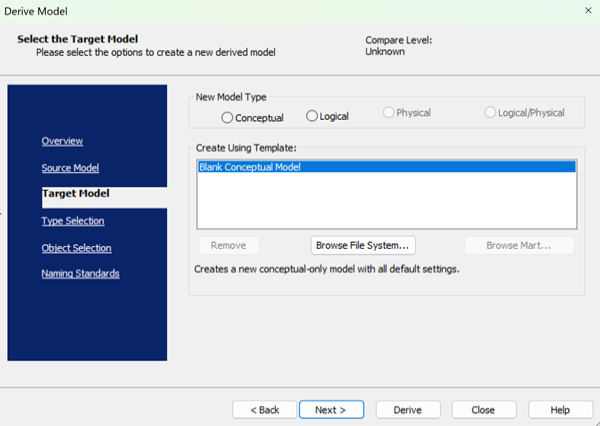
The Derive Model wizard opens on the Target Model tab, and the currently open model becomes the source model.
-
On the Target Model tab, under the New Model Type option, select the model type of target model.
Two options are available for a conceptual model:
-
Conceptual
-
Logical
-
-
Click Next or the Type Selection tab.
If you choose to keep the default selections, you can click the Derive button at any time to start the process.
-
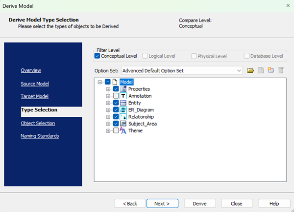
On the Type Selection tab, work with following options:
-
Filter Level: Specifies the level based on the model type selected for the target model. The filter options displayed depend on the model type you selected for the target model. For example, if the new target model is conceptual, only the Conceptual Level option is available.
-
Option Set: Specifies the set of objects that will be derived to the new model. You can open, modify, or delete an existing option set, or create a new one. You can also choose a preset option set. The following options are available:
-
Advanced Default Option Set: Includes all objects and properties for the selected derivation level.
-
Standard Default Option Set: Includes fewer objects and properties.
-
Speed Option Set: Includes fewer objects and properties for quicker selection.
-
-
-
Click Next or the Object Selection tab.
-
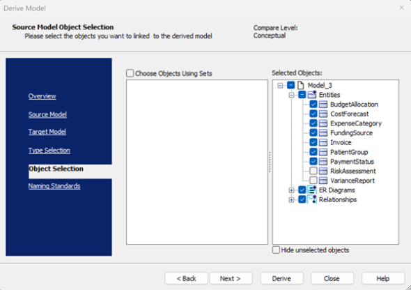
On the Object Selection tab, work with following options:
-
Choose Objects Using Sets: Specify whether to use preset options to select object set such as Entities, Relationships, or Themes. The available sets appear in a tree in the wizard. Clear this check box to use a custom set of options from the object list.
-
Selected Objects: Displays the tree of model objects for the source model. Select or clear the check box next to each object name to include or exclude it from the derived model.
-
Hide unselected objects: Hides the unselected objects.
Naming standards do not apply to conceptual models.
-
-
Click Derive.
A new model is created based on the objects you selected.
Currently, you need to manually add the derived objects to the diagram. This will be automated in a future release.
Comparing Conceptual Models
You can compare two conceptual models or compare conceptual models with logical models using the Complete Compare wizard. However, you cannot compare conceptual models with physical models or logical/physical models.
To compare two conceptual models or conceptual models with logical models, follow these steps:
-
On the ribbon, click Actions > Complete Compare.
-
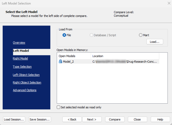
On the Left Model tab, ensure that you have selected a model.
-
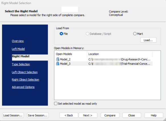
On the Right Model tab, load and select the model you want to compare.
-
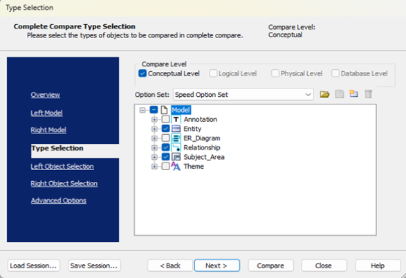
On the Type Selection tab, work with following options:
-
Compare Level: Sets the selection type for your compare, depending on the model or file you chose for the left and right pane of the selection dialog.
-
Option Set: Specifies the set of objects that will be derived to the new model. You can open, modify, or delete an existing option set, or create a new one. You can also choose a preset option set. The following options are available:
-
Advanced Default Option Set: Includes all objects and properties for the selected derivation level.
-
Standard Default Option Set: Includes fewer objects and properties.
-
Speed Option Set: Includes fewer objects and properties for quicker selection.
-
-
-
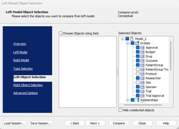
On the Left Object Selection tab, select objects for the left model and work with following options:
- Choose Objects Using Sets: Specify whether to use preset options to select object set such as Entities, Relationships, or Themes. The available sets appear in a tree in the wizard. Clear this check box to use a custom set of options from the object list.
-
Selected Objects: Displays the tree of model objects for the source model. Select or clear the check box next to each object name to include or exclude it from the derived model.
-
Hide unselected objects: Hides the unselected objects.
-
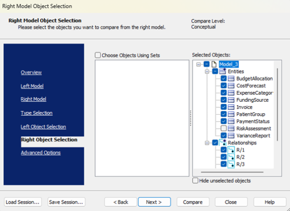
Similarly, on the Right Object Selection tab, select objects for the right model.
-
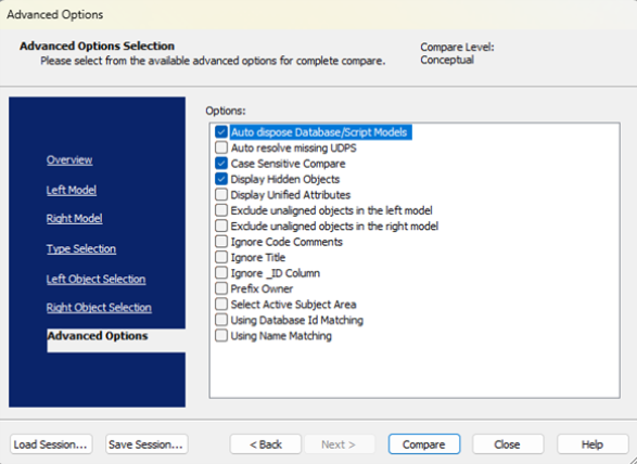
On the Advanced Options tab, select options to further refine the compare criteria.
-
Click Compare.
The Resolve Differences window opens with comparisons.
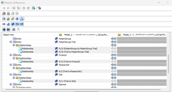
If you open the Complete Compare wizard without a model, the wizard starts on the Left Model tab. If a model is already open, it becomes the left model, and the wizard starts on the Right Model tab.
Report Designing for Conceptual Models
You can create reports using the Report Designer for conceptual models.
To generate reports, follow these steps:
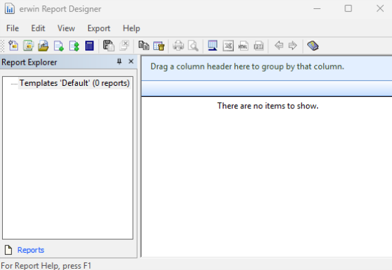
- Click Tools > Report Designer.
The erwin Report Designer window opens.
-
On the toolbar, click
to create a report solution.
If the current report solution is not saved already, you are prompted to save it. A new blank workspace appears.
-
On the toolbar, click
 to create a report.
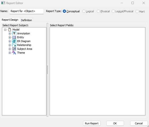
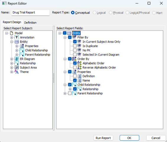
 - Enter a name for the report and in the Report Type section, click Conceptual.
- In the Select Report Subject pane, select the items for which you want to generate the report.
- In the Select Report Fields pane, select the fields that you want to include in the report.
- To create a report that filters specific objects and includes them in the report, use the Filter by option. This option is available only for entities.
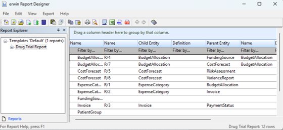
- Click Run Report.
The Report Editor window opens.
If a model is open when you launch Report Designer, the report type is set to match that model type. The items in the Select Report Subject pane change according to the Report Type that is set.
Your report is created. For more information on Report Designer, refer to the Create Reports Using Report Designer topic.